
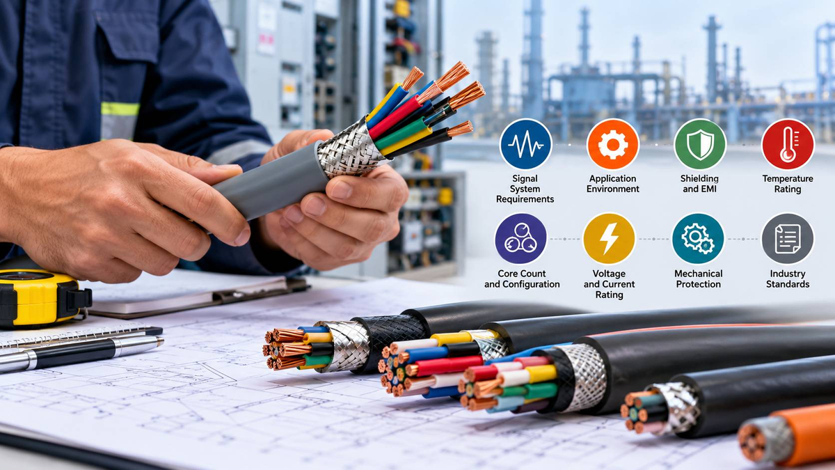
A multicore cable carries several insulated conductors inside one outer jacket, and in most plants it is the quiet link between field devices and the control system. Pressure transmitters, limit switches, valve solenoids, and temperature probes all report back through cores like these. When the cable is right, nobody notices it. When it is wrong, operators see readings that drift, PLC inputs that flicker, and network faults that come and go with the load on a nearby drive.
Most of those problems trace back to one early decision: choosing the cable by core count and price before looking at the signals it will carry. A 4 to 20 mA loop, a 24 VDC input, a thermocouple, and an RS-485 network each ask for something different from the conductors, the shielding, and the route.
This guide from CRECSO works through multicore cable selection from the signal system outward. You will learn how signal type, voltage, current, and frequency shape the choice, when foil, braid, or individually shielded pairs make sense, how US ratings such as Type TC and Type ITC fit in, and which mistakes cost the most to fix later. A checklist and an illustrative plant example are included.
What is a multicore cable?
A multicore cable is a single cable that holds two or more insulated conductors, called cores, under a common jacket. In control and instrumentation work it replaces bundles of single wires, saving tray space and installation time.
Cores can be laid up individually, twisted into pairs or triads, or grouped under their own shields. Cable built from twisted pairs is usually called multipair cable, and the twist matters, because it cancels much of the magnetic noise picked up along the run.
Why the signal system decides which multicore cable you need
The signal system sets the electrical demands on the cable: the voltage and current on each core, how fast the signal changes, and how sensitive it is to noise. Those demands decide conductor size, twisting, shielding, and whether circuits can share a jacket at all.
Compare two extremes. A 120 VAC solenoid circuit is loud and hard to disturb. A Type K thermocouple produces only about 41 microvolts per degree Celsius, so one stray millivolt of induced noise reads as an error of more than 20 degrees.
| Signal type | Typical level | Main sensitivity | Usual construction |
|---|---|---|---|
| Discrete DC I/O | 24 VDC | Voltage drop | Multiconductor |
| AC control | 120 VAC | Disturbs others | Multiconductor, kept apart |
| Analog loop | 4 to 20 mA | Ground loops, EMI | Shielded twisted pairs |
| Thermocouple | Millivolts | Any induced noise | Shielded extension pairs |
| RTD | Resistance change | Lead resistance | Shielded triads |
| RS-485 fieldbus | Differential data | Impedance, reflections | 120 ohm shielded pair |
Scroll the table sideways to see all columns.
How do voltage, current, and frequency change the cable choice?
Voltage sets the insulation rating and code category. Current sets conductor size, mostly through voltage drop. Frequency changes what matters most: low-frequency analog signals need protection from 60 Hz fields and drive harmonics, while data signals need controlled impedance and low capacitance, or the network starts throwing errors.
Can analog and digital signals share one cable?
Sometimes. A 24 VDC input and a 4 to 20 mA loop can often share individually shielded pairs if the system vendor allows it. Thermocouples should never share a jacket with 120 VAC, and the National Electrical Code (NFPA 70) limits mixing power-limited and power circuits.
How to select multicore cable: a step-by-step process
List the signals, group them by noise class, then size conductors, choose shielding, confirm ratings, and match the jacket. Core count and price come last.
- List every signalRecord type, voltage, current, frequency or data rate, and run length.
- Group by noise classPower, AC control, DC control, analog, and data usually get separate cables.
- Size the conductorsInstrument pairs are commonly 16 or 18 AWG and control circuits often 14 AWG. Check voltage drop.
- Choose the constructionPairs or triads, then foil, braid, or both, and overall or individual shields.
- Confirm the ratingMatch the voltage rating and NEC cable type (TC, ITC, PLTC) to the circuits.
- Match the jacketConsider temperature, oil, sunlight, moisture, flexing, and hazardous locations.
- Plan spares and identificationAdd spare cores and choose numbered or color-coded cores.
- Verify before buyingRead the datasheet and confirm the diameter fits glands and tray fill.
Shielding, EMI, and crosstalk in a multicore cable
Shielding keeps electromagnetic interference (EMI) from reaching the signal, and individual pair shields stop neighboring pairs from coupling into each other, which is crosstalk.
Should you choose foil, braid, or both?
| Shield | Pros | Cons | Good fit |
|---|---|---|---|
| Foil with drain | Full coverage, light, low cost | Tears under repeated flexing | Fixed instrument runs |
| Braid | Low resistance, durable | Partial coverage, slower to terminate | Machines and drive areas |
| Foil plus braid | Broad frequency protection | Highest cost and diameter | Encoders near VFDs |
Scroll the table sideways to see all columns.
Overall shield or individually shielded pairs?
An overall shield protects the bundle from outside noise but does nothing about pairs talking to each other. Belden's documentation for its Beldfoil multiple pair shielded cables notes that giving each pair its own foil shield and drain wire significantly reduces crosstalk between pairs and interference from outside sources. The tradeoff is a larger diameter, a higher price, and more drains to land.
Where should the shield be grounded?
For low-frequency analog signals, common practice is to ground the shield at one end, usually the control panel, and insulate the drain at the field end. Grounding both ends can create a ground loop. High-speed networks often bond both ends instead, so follow the equipment manufacturer's instructions.
How far should signal cables stay from power cables?
Use separate trays or a grounded metal barrier, keep VFD output cables well away from analog circuits, and cross power runs at right angles.
Conductor configuration, size, and spares
Core count comes from the signal list plus spares, stranding from how much the cable moves, and size from current and voltage drop.
How many spare cores should you include?
Many engineers plan about 10 to 20 percent spares. They absorb late design changes and damaged cores for far less than pulling a second cable.
Solid, stranded, or flexible conductors?
Standard stranded copper suits fixed tray runs. Cable carriers and robots need finely stranded, flex-rated cable, so check the rated bend radius and flex cycles.
How much does voltage drop matter on long runs?
More than people expect. 18 AWG copper has roughly 6.4 ohms of resistance per 1,000 feet. On a 500 foot run the loop is 1,000 feet, so a 0.5 A load loses about 3.2 V, more than 13 percent of a 24 VDC supply.
Operating environment and US cable ratings
In the US, the cable must carry the right NEC type and UL listing for its circuits and installation method, and its jacket must survive the site conditions. The printed jacket legend is what the inspector checks.
| Condition | What to look for |
|---|---|
| Power and control in tray | Type TC, or TC-ER where it leaves the tray without conduit |
| Instrumentation up to 150 V and 5 A | Type ITC (NEC Article 727, UL 2250) |
| Power-limited circuits | Type PLTC |
| Outdoors, oil, washdown | Sunlight resistant and oil resistant markings |
| Hazardous locations | A type the NEC permits for that class and division |
Ratings vary by manufacturer and code edition, so confirm which NEC edition your authority having jurisdiction (AHJ) enforces.
Illustrative example: a remote I/O panel at a water treatment plant
This is an illustrative scenario based on common design practice, not a documented company case study.
- Application: a remote I/O panel in a humid filter gallery, about 400 feet from the control room, near pumps on VFDs.
- Signals: 12 transmitters at 4 to 20 mA, 6 three-wire RTDs, 24 discrete inputs at 24 VDC, and 8 solenoid outputs at 120 VAC.
- Challenge: the first design put everything in two unshielded cables, placing analog loops beside switched AC loads.
- Conductor configuration: four cables with spares: 16 pairs for analog, 6 triads for RTDs, 30 conductors for DC inputs, and 12 conductors for AC outputs.
- Shielding and crosstalk: individually shielded pairs and triads with drain wires, shields grounded at the panel end only.
- Environment: 90°C conductors and a sunlight resistant jacket for a short outdoor section.
- Selected cable: Type ITC or PLTC instrumentation cable for analog and RTDs, Type TC-ER for the control circuits.
- Why it suits the job: each cable carries one noise class, and its rating matches the circuits.
- Installation: analog cables in their own tray, crossing power runs at right angles.
- Practical benefit: with this approach, analog readings stay steadier when pumps ramp, and faults are easier to trace.
Common multicore cable selection mistakes
- Choosing by core count and price before building a signal list
- Running analog loops in the same cable as 120 VAC control
- Grounding analog shields at both ends
- Using fixed-installation cable on moving machinery
- Ignoring voltage drop on long 24 VDC runs
- Approving a cheaper substitute without checking the jacket legend
Best practices checklist
- Build the signal list before the cable schedule.
- Keep one noise class per cable wherever possible.
- Use twisted pairs for every analog and data circuit.
- Use individually shielded pairs where crosstalk would hurt accuracy.
- Show the shield grounding point on the drawings.
- Keep the datasheet and jacket legend with project records.
How to get started on your next cable schedule
- Export the I/O list from the PLC or DCS design and add run lengths.
- Agree on a short list of approved cable types with your electrical and instrumentation leads.
- Ask distributors for datasheets, UL listing details, and lead times.
Future trends in signal and control cabling
Ethernet is moving closer to the field. Single Pair Ethernet under IEEE 802.3cg (10BASE-T1L) carries data up to 1,000 meters over one twisted pair, and Ethernet-APL builds on it for process instruments, including hazardous areas.
From our work on cloud server, software, and AI projects, we have seen predictive maintenance models learn from whatever sensors report, noise included. Clean signal transmission is becoming a data quality issue, not only an electrical one. Cost and device availability still limit these technologies, so most plants will run them beside conventional multicore cable for years.
Key takeaways
- The signal system, not the core count, should drive multicore cable selection.
- Separate cables by noise class and use twisted pairs for analog and data.
- Individually shielded pairs reduce crosstalk, at a higher cost.
- In the US, the NEC type and UL listing must match the circuits and installation.
Conclusion
The right multicore cable is the one built around its signals. Start from the signal list, separate circuits by how noisy or sensitive they are, then choose conductors, shielding, ratings, and jackets to suit.
CRECSO publishes practical technical guides like this one. Use the checklist above on your next cable schedule, and if you have a question or a topic you would like covered, get in touch through our contact page.
Multicore cable FAQs
What is a multicore cable used for?
It carries several control, instrument, or data circuits in one jacket, linking field devices to PLCs, DCS panels, and drives while saving tray space and labor.
What is the difference between multicore and multipair cable?
Multicore cable holds individual cores. Multipair cable twists cores into pairs, which cancels magnetic noise, so it suits analog and data signals far better.
Do 4 to 20 mA signals need shielded cable?
In most plants, yes. Twisted, shielded pairs protect the loop from drive and motor noise. Ground the shield at one end, usually at the control panel side.
Should a cable shield be grounded at both ends?
For low-frequency analog signals, usually one end only to avoid ground loops. Fast data networks often bond both ends. Follow the device maker's instructions.
What is the difference between Type TC and Type ITC cable?
Type TC is tray cable for power and control circuits. Type ITC is instrumentation tray cable limited to 150 volts and 5 amps under NEC Article 727 in the US.
How many spare cores should a multicore cable have?
Many engineers plan 10 to 20 percent spare cores. Spares cover future I/O and damaged cores, and they cost far less than pulling a second cable later on.
Can signal cables run in the same tray as power cables?
Avoid it where you can. Use separate trays or a metal barrier, keep VFD output cables well apart, and cross power runs at right angles to limit coupling.
About this guide
This is an independent educational guide. It does not replace engineering judgment, the manufacturer's instructions, or the requirements of NFPA 70 and your local authority having jurisdiction. This site does not sell cable and is not affiliated with any manufacturer named here. Last reviewed on .